4 Bit Counter Circuit Diagram
Counter bit flip using binary flops circuit output q3 q1 q2 q0 collected would final Draw a circuit diagram for 3-bit asynchronous binary down counter using Binary counter circuit diagram using ic 555 timer
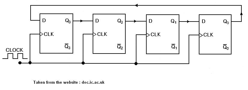
Circuit Design of a 4-bit Binary Counter Using D Flip-flops – VLSIFacts
Counter synchronous bit diagram circuit electronics Counter circuit 555 timer binary diagram circuits wiring electronic diagrams switch based schematic projects ic using wire center gates gate Vhdl coding tips and tricks: example : 4 bit ring counter with testbench
4 bit up down counter truth table
Bit asynchronous counter down diagram circuit draw flip using jk binary flops ff16. the 4 bit synchronous up counter circuit constructed with t 4-bit ripple counterCircuit diagram of 3-bit synchronous counter.
State flop binary circuit flops truth constructDiagram counter down bit block circuit precautions Bit 4bit countersCounter bit ripple circuit electronics circuits simulator simulation.

Ring counter bit verilog code vhdl diagram example tips testbench ckt tricks coding written
Synchronous flops constructedCircuit design of a 4-bit binary counter using d flip-flops – vlsifacts Circuit design of a 4-bit binary counter using d flip-flops.
.


Binary Counter Circuit Diagram using IC 555 Timer

DeldSim - 4-Bit Down Counter

Circuit Design of a 4-bit Binary Counter Using D Flip-flops - VLSIFacts

16. The 4 bit synchronous up counter circuit constructed with T

4 Bit Up Down Counter Truth Table | Letter G Decoration
VHDL coding tips and tricks: Example : 4 bit Ring Counter with testbench

circuit diagram of 3-bit synchronous counter - Electronics Coach

Circuit Design of a 4-bit Binary Counter Using D Flip-flops – VLSIFacts